Benefits at a glance:
- maximum straightness deviation of 0.6 mm/3 m
- outstanding purity grade
- consistent, specially adapted microstructure
- exact edge geometry
- also small quantities can be supplied fast
Doctor Blade Steel
Our strip steel for doctor blades uses high grade steel and is manufactured with precision, making it a key component for ensuring reliable processes in the printing industry. Manufacturers of doctor blades used in gravure or flexographic printing for example, appreciate the consistent quality of our strip steel for doctor blades. It can be reliably processed and its precision guarantees that the products made from it are of excellent quality. To find out more please call us – we will be very happy to take your call!
| Parameters | Recommendation | |
|---|---|---|
| Thickness tolerance | T2 | |
| Tensile strength | range M | |
| Flatness | class 3 | |
| Surface | white polished | |
| Edges | rounded | |
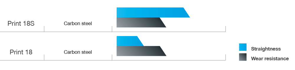
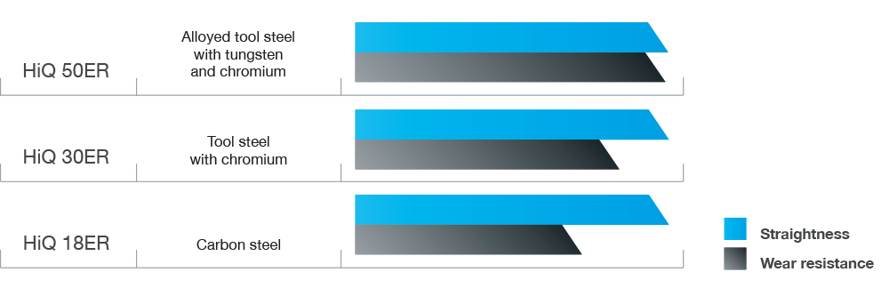
| Grade | HiQ 50ER, HiQ 30ER, HiQ 18ER | |
| Straightness | HiQ 50ER, HiQ 30ER, HiQ 18ER | class 5 |
| Print 18S | class 4 | |
| Print 18 | class 3 | |
| Thickness t (in) | Tolerances ± in | ||||
| T1 | T2 | T3 | T4 | T5 | |
| .0008 ≤ t < .0016 | .00016 | .00012 | .00008 | .00006 | – |
| .0016 ≤ t < .0025 | .00020 | .00016 | .00012 | .00008 | – |
| .0025 ≤ t < .0039 | .00024 | .00020 | .00016 | .00012 | .00008 |
| .0039 ≤ t < .0049 | .00028 | .00020 | .00016 | .00012 | .00008 |
| .0049 ≤ t < .0063 | .00035 | .00024 | .00020 | .00016 | .00012 |
| .0063 ≤ t < .0079 | .00039 | .00028 | .00020 | .00016 | .00012 |
| .0079 ≤ t < .0098 | .00043 | .00031 | .00024 | .00016 | .00012 |
| .0098 ≤ t < .0124 | .00051 | .00035 | .00028 | .00020 | .00016 |
| .0124 ≤ t < .0157 | .00059 | .00043 | .00031 | .00024 | .00016 |
| .0157 ≤ t < .0197 | .00067 | .00047 | .00035 | .00024 | .00016 |
| .0197 ≤ t < .0248 | .00079 | .00055 | .00039 | .00028 | .00020 |
| .0248 ≤ t < .0315 | .00091 | .00067 | .00047 | .00031 | .00024 |
| .0315 ≤ t < .0394 | .00106 | .00075 | .00051 | .00035 | .00028 |
| .0394 ≤ t < .0492 | .00134 | .00094 | .00067 | .00047 | .00031 |
| .0492 ≤ t < .0630 | .00154 | .00110 | .00079 | – | – |
| .0630 ≤ t < .0689 | .00181 | .00130 | .00091 | – | – |
| Thickness t (mm) | Tolerances ± mm | ||||
| T1 | T2 | T3 | T4 | T5 | |
| 0,020 ≦ t < 0,040 | 0,004 | 0,003 | 0,002 | 0,002 | – |
| 0,040 ≦ t < 0,063 | 0,005 | 0,004 | 0,003 | 0,002 | – |
| 0,063 ≦ t < 0,100 | 0,006 | 0,005 | 0,004 | 0,003 | 0,002 |
| 0,100 ≦ t < 0,125 | 0,007 | 0,005 | 0,004 | 0,003 | 0,002 |
| 0,125 ≦ t < 0,160 | 0,009 | 0,006 | 0,005 | 0,004 | 0,003 |
| 0,160 ≦ t < 0,200 | 0,010 | 0,007 | 0,005 | 0,004 | 0,003 |
| 0,200 ≦ t < 0,250 | 0,011 | 0,008 | 0,006 | 0,004 | 0,003 |
| 0,250 ≦ t < 0,315 | 0,013 | 0,009 | 0,007 | 0,005 | 0,004 |
| 0,315 ≦ t < 0,400 | 0,015 | 0,011 | 0,008 | 0,006 | 0,004 |
| 0,400 ≦ t < 0,500 | 0,017 | 0,012 | 0,009 | 0,006 | 0,004 |
| 0,500 ≦ t < 0,630 | 0,020 | 0,014 | 0,010 | 0,007 | 0,005 |
| 0,630 ≦ t < 0,800 | 0,023 | 0,017 | 0,012 | 0,008 | 0,006 |
| 0,800 ≦ t < 1,000 | 0,027 | 0,019 | 0,013 | 0,009 | 0,007 |
| 1,000 ≦ t < 1,250 | 0,034 | 0,024 | 0,017 | 0,012 | 0,008 |
| 1,250 ≦ t < 1,600 | 0,039 | 0,028 | 0,020 | – | – |
| 1,600 ≦ t ≦ 1,750 | 0,046 | 0,033 | 0,023 | – | – |
| Thickness t (in) | Width w (in) | Tolerances ± in | ||
| B1 | B2 | B3 | ||
| t < .0098 | w < .79 | .003 | .002 | .001 |
| .79 ≤ w < 1.97 | .004 | .003 | .002 | |
| 1.97 ≤ w < 4.92 | .006 | .004 | .003 | |
| w ≥ 4.92 | .008 | .006 | .004 | |
| .0098 ≤ t < .0197 | w < .79 | .004 | .003 | .002 |
| .79 ≤ w < 1.97 | .006 | .004 | .003 | |
| 1.97 ≤ w < 4.92 | .008 | .006 | .004 | |
| w ≥ 4.92 | .010 | .008 | .006 | |
| .0197 ≤ t < .0394 | w < .79 | .006 | .004 | .003 |
| .79 ≤ w < 1.97 | .008 | .006 | .004 | |
| 1.97 ≤ w < 4.92 | .010 | .008 | .006 | |
| w ≥ 4.92 | .012 | .010 | .006 | |
| .0394 ≤ t < .0630 | w < .79 | .008 | .006 | .004 |
| .79 ≤ w < 1.97 | .010 | .008 | .006 | |
| 1.97 ≤ w < 4.92 | .012 | .010 | .006 | |
| w ≥ 4.92 | .014 | .010 | .008 | |
| .0630 ≤ t ≦ .0689 | w < .79 | .010 | .008 | .006 |
| .79 ≤ w < 1.97 | .012 | .008 | .006 | |
| 1.97 ≤ w < 4.92 | .014 | .012 | .008 | |
| w ≥ 4.92 | .016 | .012 | .008 | |
| Thickness t mm | Width w mm | Tolerances ± mm | ||
| B1 | B2 | B3 | ||
| t < 0,25 | w < 20,00 | 0,07 | 0,05 | 0,03 |
| 20,00 ≦ w < 50,00 | 0,10 | 0,07 | 0,05 | |
| 50,00 ≦ w < 125,00 | 0,15 | 0,11 | 0,07 | |
| w ≧ 125,00 | 0,20 | 0,15 | 0,10 | |
| 0,25 ≦ t < 0,5 | w < 20,00 | 0,10 | 0,07 | 0,05 |
| 20,00 ≦ w < 50,00 | 0,15 | 0,11 | 0,07 | |
| 50,00 ≦ w < 125,00 | 0,20 | 0,15 | 0,10 | |
| w ≧ 125,00 | 0,25 | 0,20 | 0,15 | |
| 0,5 ≦ t < 1,0 | w < 20,00 | 0,15 | 0,11 | 0,07 |
| 20,00 ≦ w < 50,00 | 0,20 | 0,15 | 0,10 | |
| 50,00 ≦ w < 125,00 | 0,25 | 0,20 | 0,15 | |
| w ≧ 125,00 | 0,30 | 0,25 | 0,15 | |
| 1,0 ≦ t < 1,6 | w < 20,00 | 0,20 | 0,15 | 0,10 |
| 20,00 ≦ w < 50,00 | 0,25 | 0,20 | 0,15 | |
| 50,00 ≦ w < 125,00 | 0,30 | 0,25 | 0,15 | |
| w ≧ 125,00 | 0,35 | 0,25 | 0,20 | |
| 1,6 ≦ t ≦ 1,75 | w < 20,00 | 0,25 | 0,20 | 0,15 |
| 20,00 ≦ w < 50,00 | 0,30 | 0,20 | 0,15 | |
| 50,00 ≦ w < 125,00 | 0,35 | 0,30 | 0,20 | |
| w ≧ 125,00 | 0,40 | 0,30 | 0,20 | |
Available in white, blue and yellow
Surface Roughness
| Thickness t (in) | Roughness (nach DIN EN ISO 4287 : 1998) | ||
| Class 1 | Class 2 | Class 3 | |
| t ≤ .0197 | Ra ≦ 11.8 µin Rt ≦ 118 µin |
Ra ≦ 9.8 µin Rt ≦ 98 µin |
Ra ≦ 5.1 µin Rt ≦ 59 µin |
| .0197 < t ≤ .0276 | Ra ≦ 7.9 µin Rt ≦ 79 µin |
||
| .0276 < t ≤ .0394 | Ra ≦ 13.8 µin Rt ≦ 138 µin |
||
| .0394 < t ≤ .0689 | Ra ≦ 15.7 µin Rt ≦ 157 µin |
Ra ≦ 13.8 µin Rt ≦ 138 µin |
Ra ≦ 11.8 µin Rt ≦ 118 µin |
Available in white, blue and yellow
Surface Roughness
| Thickness t mm | Roughness (nach DIN EN ISO 4287 : 1998) | ||
| Class 1 | Class 2 | Class 3 | |
| t ≦ 0,500 | Ra ≦ 0,30 µm Rt ≦ 3,00 µm |
Ra ≦ 0,25 µm Rt ≦ 2,50 µm |
Ra ≦ 0,13 µm Rt ≦ 1,50 µm |
| 0,500 < t ≦ 0,700 | Ra ≦ 0,20 µm Rt ≦ 2,00 µm |
||
| 0,700 < t ≦ 1,000 | Ra ≦ 0,35 µm Rt ≦ 3,50 µm |
||
| 1,000 < t ≦ 1,750 | Ra ≦ 0,40 µm Rt ≦ 4,00 µm |
Ra ≦ 0,30 µm Rt ≦ 3,00 µm |
Ra ≦ 0,30 µm Rt ≦ 3,00 µm |
| Thickness t (in) | Tensile Strength MPa | Eberle Tolerance +/- | ||
|---|---|---|---|---|
| Range L | Range M | Range H | ||
| .0008 ≤ t < .0039 | – | HV630 | – | HV25 |
| .0039 ≤ t < .0049 | 1800 | 2100 | 2300 | 50 |
| .0049 ≤ t < .0069 | 1800 | 2050 | 2250 | 50 |
| .0069 ≤ t < .0089 | 1750 | 2000 | 2200 | 50 |
| .0089 ≤ t < .0108 | 1750 | 1950 | 2200 | 50 |
| .0108 ≤ t < .0148 | 1700 | 1900 | 2150 | 50 |
| .0148 ≤ t < .0167 | 1650 | 1850 | 2100 | 50 |
| .0167 ≤ t < .0187 | 1600 | 1800 | 2050 | 50 |
| .0187 ≤ t < .0207 | 1550 | 1750 | 2000 | 50 |
| .0207 ≤ t < .0246 | 1550 | 1750 | 2000 | 50 |
| .0246 ≤ t < .0285 | 1500 | 1700 | 1950 | 50 |
| .0285 ≤ t < .0325 | 1500 | 1700 | 1950 | 50 |
| .0325 ≤ t < .0364 | 1450 | 1650 | 1900 | 50 |
| .0364 ≤ t < .0404 | 1450 | 1650 | 1900 | 50 |
| .0404 ≤ t < .0453 | 1450 | 1650 | 1900 | 50 |
| .0453 ≤ t < .0492 | 1400 | 1600 | 1850 | 50 |
| .0492 ≤ t < .0531 | 1400 | 1600 | 1850 | 50 |
| .0531 ≤ t < .0620 | 1400 | 1600 | 1850 | 50 |
| .0620 ≤ t ≤ .0689 | 1350 | 1550 | 1800 | 50 |
| Thickness t (mm) | Tensile Strenght MPa | Eberle Tolerance +/- | ||
|---|---|---|---|---|
| Range L | Range M | Range H | ||
| 0,020 ≤ t < 0,100 | – | HV630 | – | HV25 |
| 0,100 ≤ t < 0,125 | 1800 | 2100 | 2300 | 50 |
| 0,125 ≤ t < 0,175 | 1800 | 2050 | 2250 | 50 |
| 0,175 ≤ t < 0,225 | 1750 | 2000 | 2200 | 50 |
| 0,225 ≤ t < 0,275 | 1750 | 1950 | 2200 | 50 |
| 0,275 ≤ t < 0,375 | 1700 | 1900 | 2150 | 50 |
| 0,375 ≤ t < 0,425 | 1650 | 1850 | 2100 | 50 |
| 0,425 ≤ t < 0,475 | 1600 | 1800 | 2050 | 50 |
| 0,475 ≤ t < 0,525 | 1550 | 1750 | 2000 | 50 |
| 0,525 ≤ t < 0,625 | 1550 | 1750 | 2000 | 50 |
| 0,625 ≤ t < 0,725 | 1500 | 1700 | 1950 | 50 |
| 0,725 ≤ t < 0,825 | 1500 | 1700 | 1950 | 50 |
| 0,825 ≤ t < 0,925 | 1450 | 1650 | 1900 | 50 |
| 0,925 ≤ t < 1,025 | 1450 | 1650 | 1900 | 50 |
| 1,025 ≤ t < 1,150 | 1450 | 1650 | 1900 | 50 |
| 1,150 ≤ t < 1,250 | 1400 | 1600 | 1850 | 50 |
| 1,250 ≤ t < 1,350 | 1400 | 1600 | 1850 | 50 |
| 1,350 ≤ t < 1,575 | 1400 | 1600 | 1850 | 50 |
| 1,575 ≤ t ≤ 1,750 | 1350 | 1550 | 1800 | 50 |
| Thickness t in | Flatness deviation P | |||
| Class 1 | Class 2 | Class 3 | Class 4 | |
| .0008 ≦ t < .0039 | P60 | P50 | P40 | P30 |
| .0039 ≦ t < .0079 | P50 | P40 | P30 | P20 |
| .0079 ≦ t < .0138 | P45 | P35 | P25 | P15 |
| .0138 ≦ t < .0197 | P40 | P30 | P20 | P10 |
| .0197 ≦ t ≦ .0689 | P35 | P25 | P15 | P10 |
P15 means maximum flatness deviation of .0015 in per 1 in strip width.
| Thickness t mm | Flatness Deviation P | |||
| Class 1 | Class 2 | Class 3 | Class 4 | |
| 0,020 ≦ t < 0,100 | P60 | P50 | P40 | P30 |
| 0,100 ≦ t < 0,200 | P50 | P40 | P30 | P20 |
| 0,200 ≦ t < 0,350 | P45 | P35 | P25 | P15 |
| 0,350 ≦ t < 0,500 | P40 | P30 | P20 | P10 |
| 0,500 ≦ t ≦1,750 | P35 | P25 | P15 | P10 |
P15 means maximum flatness deviation of 1,5 µm per 1 mm strip width.
| Strip width w (in) | Measured lenght (ft) | Class 3 (in) | Class 4 (in) | Class 5 (in) |
| w < .591 | 1.6 | .063 | .031 | .024 |
| .591 ≤ w < 1.378 | 3.3 | .071 | .035 | .024 |
| 10 | .142 | .071 | .047 | |
| 1.378 ≤ w < 4.921 | 3.3 | .047 | .024 | .012 |
| 10 | .094 | .047 | .024 | |
| 4.921 ≤ w ≤ 9.843 | 3.3 | .047 | – | – |
G0,6/3 means maximum straightness deviation of .024 in over a measuring length of 10 ft.
| Strip width w (mm) | Measured lenght (m) | Class 3 (mm) | Class 4 (mm) | Class 5 (mm) |
| w < 15,00 | 0,5 | 1,6 | 0,8 | 0,6 |
| 15,00 ≤ w < 35,00 | 1 | 1,8 | 0,9 | 0,6 |
| 3 | 3,6 | 1,8 | 1,2 | |
| 35,00 ≤ w < 125,00 | 1 | 1,2 | 0,6 | 0,3 |
| 3 | 2,4 | 1,2 | 0,6 | |
| 125,00 ≤ w ≤ 250,00 | 1 | 1,2 | – | – |
G0,6/3 means maximum straightness deviation of 0,6 mm over a measuring length of 3 m.
| Grade | Chemical Composition (percent nominal) | Comparison of Norms | |||||
|---|---|---|---|---|---|---|---|
| C | Si | Mn | Cr | DIN | Material-No. | US-Norm | |
| HiQ 50ER | on request | on request | on request | on request | on request | on request | on request |
| HiQ 30ER | 1,05 | 0,25 | 0,30 | 1,50 | 102Cr6 | 1.2067 | – |
| HiQ 18ER Print 18S Print 18 |
1,00 | 0,25 | 0,40 | – | C100S | 1.1274 | AISI 1095 |
| KG, KE |  |
Slit .079 ≤ w ≤ 9.843 in 2,00 ≤ w ≤ 250,00 mm Deburred t < .026 in: .157 ≤ w ≤ 9.843 in t ≥ .026 in: .157 ≤ w ≤ 5.906 in0,65 mm: 4,00 ≤ w ≤ 250,00 mm t ≥ 0,65 mm: 4,00 ≤ w ≤ 150,00 mm |
| K2 |  |
Bevelled t ≥ .012 in .394 ≤ w ≤ 5.906 int ≥ 0,30 mm 10,00 ≤ w ≤ 150,00 mm Tip: s Bevel angle: x |
| K3 |  |
Rectangular rounded t ≥ .006 in .236 ≤ w ≤ 5.906 int ≥ 0,15 mm 6,00 ≤ w ≤ 150,00 mm Standard radiuses r .006 ≤ t < .010 in : .0016 in .010≤ t < .031 in : .0031 in .031 ≤ t < .050 in : .0059 in .050 ≤ t ≤ .069 in : .0078 in 0,15 ≤ t < 0,25 mm : 0,04 mm |
| K4 |  |
Rounded t ≥ .0024 in .157 ≤ w ≤ 5.906 int ≥ 0,06 mm 4,00 ≤ w ≤ 150,00 mm |
We supply the appropriate steel grades and processing for each type of doctor blade that you manufacture.
The special characteristics of our High Quality grades are determined by:
- max. straightness deviation of .024 in/10 ft
- superior purity grade
- constant and specially adapted microstructure
- best flatness metrics
- exact edge geometries
Our Print grades feature the following winning criteria:
- defined straightness
- constant microstructure
- best flatness
- exact edge geometries